Power Systems0 / 12 done
Questions per paper
- All
- MCQ
- MSQ
- NAT
2015 to 2026. Point at a year to read it.
Show as a table
| Year | All | MCQ | MSQ | NAT |
|---|---|---|---|---|
| 2015 | 0 | 0 | 0 | 0 |
| 2016 | 1 | 0 | 0 | 1 |
| 2017 | 1.5 | 0 | 0 | 1.5 |
| 2018 | 0 | 0 | 0 | 0 |
| 2019 | 1 | 0 | 0 | 1 |
| 2020 | 1 | 0 | 0 | 1 |
| 2021 | 2 | 1 | 0 | 1 |
| 2022 | 2 | 1 | 0 | 1 |
| 2023 | 1 | 0 | 0 | 1 |
| 2024 | 0 | 0 | 0 | 0 |
| 2025 | 0 | 0 | 0 | 0 |
| 2026 | 1 | 0 | 1 | 0 |
- 1EE 2026 · 2 marks · MSQ · ModerateFor the balanced 3-phase transmission line shown, consider the following cases:
- 2EE 2023 · 1 mark · NAT · HardA , line of length has the following parameters:
- 3EE 2022 · 1 mark · MCQ · HardThe geometric mean radius of a conductor, having four equal strands with each strand of radius '', as shown in the figure below, is
- 4EE 2022 · 1 mark · NAT · EasyIf only of the supplied power to a cable reaches the output terminal, the power loss in the cable, in decibels, is _____. (round off to nearest integer)
- 5EE 2021 · 1 mark · NAT · ModerateTwo single-core power cables have total conductor resistances of and , respectively, and their insulation resistances (between core and sheath) are and , respectively. When the two cables are joined in series, the ratio of insulation resistance to conductor resistance is .
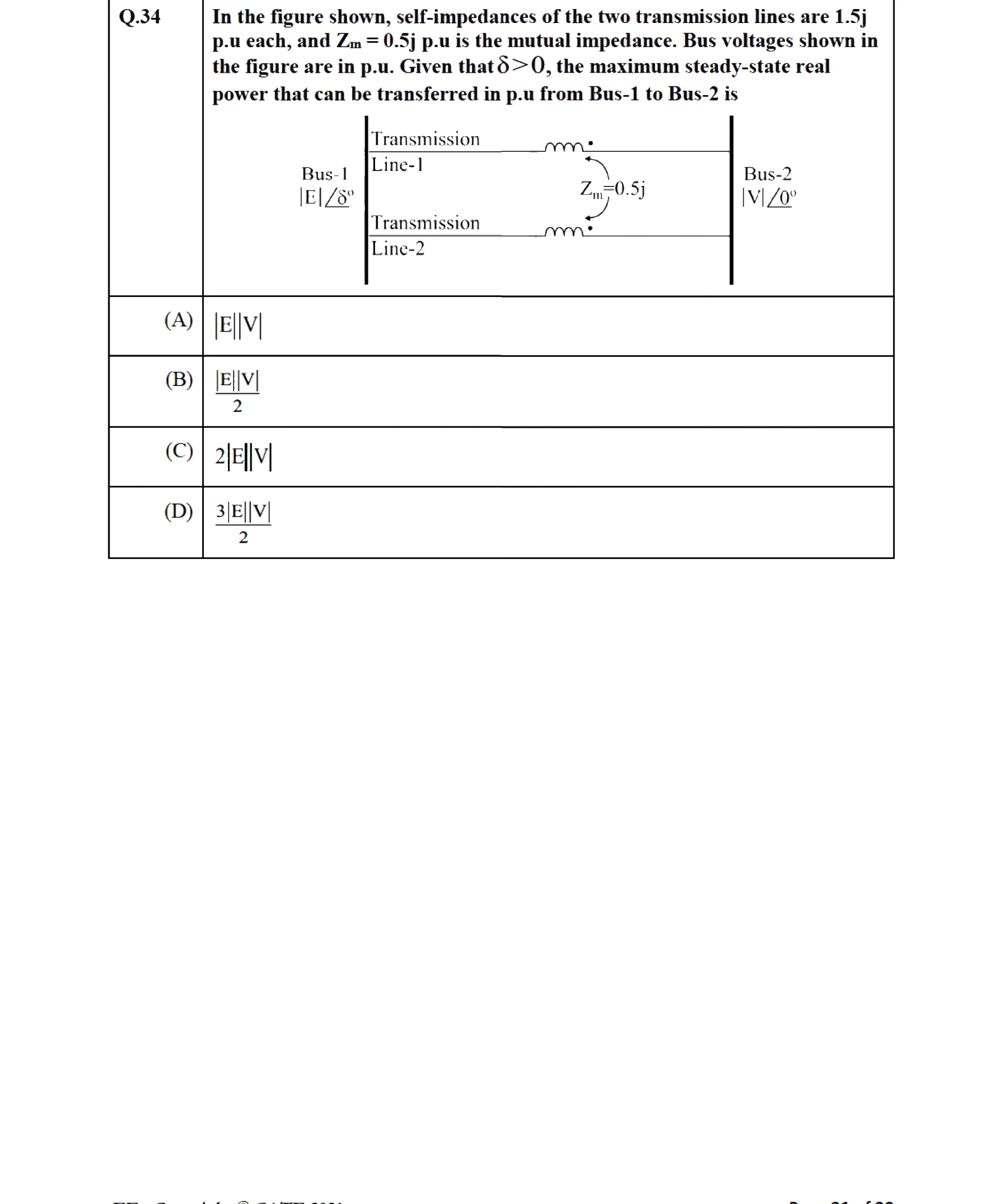
- 6EE 2021 · 2 marks · MCQ · ModerateIn the figure shown, self-impedances of the two transmission lines are each, and is the mutual impedance. Bus voltages shown in the figure are in p.u. Given that , the maximum steady-state real power that can be transferred in p.u from Bus-1 to Bus-2 is
- 7EE 2020 · 2 marks · NAT · ModerateBus 1 with voltage magnitude is sending reactive power towards bus 2 with voltage magnitude through a lossless transmission line of reactance . Keeping the voltage at bus 2 fixed at , magnitude of voltage at bus 1 is changed, so that the reactive power sent from bus 1 is increased by . Real power flow through the line under both the conditions is zero. The new value of the voltage magnitude, , in (rounded off to decimal places), at bus 1 is ____.
- 8EE 2019 · 2 marks · NAT · ModerateA three-phase , transmission line is long. The line inductance is per phase, and the capacitance is per phase. The line is under open circuit condition at the receiving end and energized with at the sending end, the receiving end line voltage in (round off to two decimal places) will be ____.
- 9EE 2017 Set 2 · 1 mark · NAT · ModerateThe nominal- circuit of a transmission line is shown in the figure.
- 10EE 2017 Set 2 · 2 marks · NAT · ModerateConsider an overhead transmission line with -phase, balanced system with conductors located at the vertices of an equilateral triangle of length as shown in figure below. The resistances of the conductors are neglected. The geometric mean radius (GMR) of each conductor is . Neglecting the effect of ground, the magnitude of positive sequence reactance in (rounded off to three decimal places) is ______
- 11EE 2017 Set 2 · 2 marks · NAT · ModerateA 3-phase, generator supplies power of at to a balanced 3-phase inductive load through an overhead line. The per phase line resistance and reactance are and respectively. If the voltage at the generator terminal is , the power factor of the load is ____.
- 12EE 2016 Set 2 · 2 marks · NAT · ModerateAt no load condition, a 3-phase, , lossless power transmission line has sending-end and receiving-end voltages of and respectively. Assuming the velocity of traveling wave to be the velocity of light, the length of the line, in , is ____.