72 questions0 / 72 done
Questions per paper
- All
- MCQ
- MSQ
- NAT
2015 to 2026. Point at a year to read it.
Show as a table
| Year | All | MCQ | MSQ | NAT |
|---|---|---|---|---|
| 2015 | 0 | 0 | 0 | 0 |
| 2016 | 7 | 2 | 0 | 5 |
| 2017 | 3.5 | 0.5 | 0 | 3 |
| 2018 | 7 | 4 | 0 | 3 |
| 2019 | 6 | 0 | 0 | 6 |
| 2020 | 6 | 3 | 0 | 3 |
| 2021 | 7 | 5 | 0 | 2 |
| 2022 | 7 | 4 | 0 | 3 |
| 2023 | 6 | 3 | 1 | 2 |
| 2024 | 6 | 2 | 2 | 2 |
| 2025 | 6 | 2 | 0 | 4 |
| 2026 | 7 | 5 | 1 | 1 |
- 1EE 2026 · 1 mark · MCQ · ModerateConsider a power system with buses, of which are generator buses and the remaining are load buses (where there is no generation).
- 2EE 2026 · 1 mark · MCQ · ModerateThe initial three-phase voltage phasors (, , and ) at a bus of a power network are as shown in Case-1. Due to a disturbance, the bus voltage phasors changed in phase by a small angle , and the magnitudes remained the same as depicted in Case-2.
- 3EE 2026 · 2 marks · MCQ · HardIn the circuit shown, the phase currents are
- 4EE 2026 · 2 marks · MCQ · ModerateThe operating characteristic of a reactance relay is given by , where is the reactance calculated by the relay. Its operating characteristic in the admittance plane (- plane, where and denote conductance and susceptance, respectively, expressed in ) is given by:
- 5EE 2026 · 2 marks · MCQ · ModerateA three-phase two-winding transformer has a voltage transformation ratio , where is the primary side voltage in p.u., and is the secondary side voltage in p.u. and represent the currents injected into the primary and secondary sides of the transformer, respectively. The admittance corresponding to the leakage impedance of the transformer referred to the secondary is p.u. Neglect the magnetizing branch.
- 6EE 2026 · 2 marks · MSQ · ModerateFor the balanced 3-phase transmission line shown, consider the following cases:
- 7EE 2026 · 2 marks · NAT · ModerateA system with two generators and (without generator limits) is shown.
- 8EE 2025 · 1 mark · MCQ · EasyDuring a power failure, a domestic household uninterruptible power supply (UPS) supplies AC power to a limited number of lights and fans in various rooms. As per a Newton-Raphson load-flow formulation, the UPS would be represented as a
- 9EE 2025 · 1 mark · NAT · ModerateConsider a distribution feeder, with ratio of . At the receiving end, a load is connected. The maximum voltage drop will occur from the sending end to the receiving end, when the power factor of the load is _____(round off to three decimal places).
- 10EE 2025 · 1 mark · NAT · ModerateThe bus impedance matrix of a 3-bus system (in ) is
- 11EE 2025 · 2 marks · MCQ · ModerateIn the system shown below, the generator was initially supplying power to the grid. A temporary LLLG bolted fault occurs at F very close to circuit breaker 1. The circuit breakers open to isolate the line. The fault self-clears. The circuit breakers reclose and restore the line. Which one of the following diagrams best indicates the rotor accelerating and decelerating areas?
- 12EE 2025 · 2 marks · NAT · ModerateUsing shunt capacitors, the power factor of a 3-phase, induction motor (drawing at ) is to be corrected to . The line current of the capacitor bank, in , is ________ (round off to one decimal place).
- 13EE 2025 · 2 marks · NAT · HardTwo units, rated at and , are enabled for economic load dispatch. When the overall incremental cost is , the units are dispatched to and respectively. At an overall incremental cost of , the power output of the units are and , respectively. The total plant MW-output (without overloading any unit) at an overall incremental cost of is ______ (round off to the nearest integer).
- 14EE 2024 · 1 mark · MCQ · HardThe figure shows the single line diagram of a 4-bus power network. Branches , , , and have impedances , , , and per-unit (pu), respectively, where , with and . The current drawn from each load bus (marked as arrows) is equal to , where . If the network is to operate with minimum loss, the branch that should be opened is
- 15EE 2024 · 1 mark · NAT · ModerateThe incremental cost curves of two generators (Gen A and Gen B) in a plant supplying a common load are shown in the figure. If the incremental cost of supplying the common load is Rs. 7400 per , then the common load in is ____ (rounded off to the nearest integer).
- 16EE 2024 · 2 marks · MCQ · ModerateFor the three-bus lossless power network shown in the figure, the voltage magnitudes at all the buses are equal to 1 per unit (pu), and the differences of the voltage phase angles are very small. The line reactances are marked in the figure, where , , , and are strictly positive. The bus injections and are in pu. If , where , and the real power flow from bus 1 to bus 2 is , then which one of the following options is correct?
- 17EE 2024 · 2 marks · MSQ · ModerateFor a two-phase network, the phase voltages and are to be expressed in terms of sequence voltages and as . The possible option(s) for matrix is/are
- 18EE 2024 · 2 marks · MSQ · EasyWhich of the following options is/are correct for the Automatic Generation Control (AGC) and Automatic Voltage Regulator (AVR) installed with synchronous generators?
- 19EE 2024 · 2 marks · NAT · ModerateThe single line diagram of a lossless system is shown in the figure. The system is operating in steady-state at a stable equilibrium point with the power output of the generator being , where is the load angle and the mechanical power input is . A fault occurs on line 2 such that the power output of the generator is less than during the fault. After the fault is cleared by opening line 2, the power output of the generator is . If the critical fault clearing angle is radians, the accelerating area on the power angle curve is ____ times (rounded off to 2 decimal places).
- 20EE 2023 · 1 mark · MCQ · HardFor the three-bus power system shown in the figure, the trip signals to the circuit breakers to are provided by overcurrent relays to , respectively, some of which have directional properties also. The necessary condition for the system to be protected for short circuit fault at any part of the system between bus 1 and the loads with isolation of minimum portion of the network using minimum number of directional relays is
- 21EE 2023 · 1 mark · MCQ · HardThe expressions of fuel cost of two thermal generating units as a function of the respective power generation and are given as where is a constant. For a given value of , optimal dispatch requires the total load of to be shared as and . With the load remaining unchanged, the value of is increased by and optimal dispatch is carried out. The changes in and the total cost of generation, in will be as follows
- 22EE 2023 · 1 mark · MSQ · HardThe bus admittance () matrix of a 3-bus power system is given below.
- 23EE 2023 · 1 mark · NAT · HardA , line of length has the following parameters:
- 24EE 2023 · 2 marks · MCQ · ModerateThe three-bus power system shown in the figure has one alternator connected to bus 2 which supplies and power. Bus 3 is infinite bus having a voltage of magnitude and angle of . A variable current source, is connected at bus 1 and controlled such that the magnitude of the bus 1 voltage is maintained at and the phase angle of the source current, , where is the phase angle of the bus 1 voltage. The three buses can be categorized for load flow analysis as
- 25EE 2023 · 2 marks · NAT · HardThe two-bus power system shown in figure (i) has one alternator supplying a synchronous motor load through a - transformer. The positive, negative and zero-sequence diagrams of the system are shown in figures (ii), (iii) and (iv), respectively. All reactances in the sequence diagrams are in For a bolted line-to-line fault (fault impedance = zero) between phases 'b' and 'c' at bus 1, neglecting all pre-fault currents, the magnitude of the fault current (from phase 'b' to 'c') in is ________ (Round off to 2 decimal places).
- 26EE 2022 · 1 mark · MCQ · ModerateThe most commonly used relay, for the protection of an alternator against loss of excitation, is
- 27EE 2022 · 1 mark · MCQ · HardThe geometric mean radius of a conductor, having four equal strands with each strand of radius '', as shown in the figure below, is
- 28EE 2022 · 1 mark · MCQ · EasyThe valid positive, negative and zero sequence impedances (in p.u.), respectively, for a , fully transposed three-phase transmission line, from the given choices are
- 29EE 2022 · 1 mark · NAT · EasyIf only of the supplied power to a cable reaches the output terminal, the power loss in the cable, in decibels, is _____. (round off to nearest integer)
- 30EE 2022 · 2 marks · MCQ · EasyThe fuel cost functions in for two thermal power plants are given by
- 31EE 2022 · 2 marks · NAT · ModerateTwo generating units rated for and have governor speed regulations of and , respectively, from no load to full load. Both the generating units are operating in parallel to share a load of . Assuming free governor action, the load shared in , by the generating unit is _____. (round off to nearest integer)
- 32EE 2022 · 2 marks · NAT · ModerateA , , -pole, alternator has an inertia constant of . If the input and output powers of the alternator are and , respectively, the angular acceleration in mechanical degree/ is ___________. (round off to nearest integer)
- 33EE 2021 · 1 mark · MCQ · ModerateConsider a power system consisting of number of buses. Buses in this power system are categorized into slack bus, PV buses and PQ buses for load flow study. The number of PQ buses is . The balanced Newton-Raphson method is used to carry out load flow study in polar form. , , , and are sub-matrices of the Jacobian matrix as shown below:
- 34EE 2021 · 1 mark · MCQ · EasyTwo generators have cost functions and . Their incremental-cost characteristics are They need to deliver a combined load of . Ignoring the network losses, for economic operation, the generations and (in ) are
- 35EE 2021 · 1 mark · NAT · ModerateTwo single-core power cables have total conductor resistances of and , respectively, and their insulation resistances (between core and sheath) are and , respectively. When the two cables are joined in series, the ratio of insulation resistance to conductor resistance is .
- 36EE 2021 · 1 mark · NAT · EasyAn alternator with internal voltage of and synchronous reactance of is connected by a transmission line of reactance to a synchronous motor having synchronous reactance and internal voltage of . If the real power supplied by the alternator is , then is ____ degrees. (Round off to 2 decimal places.)
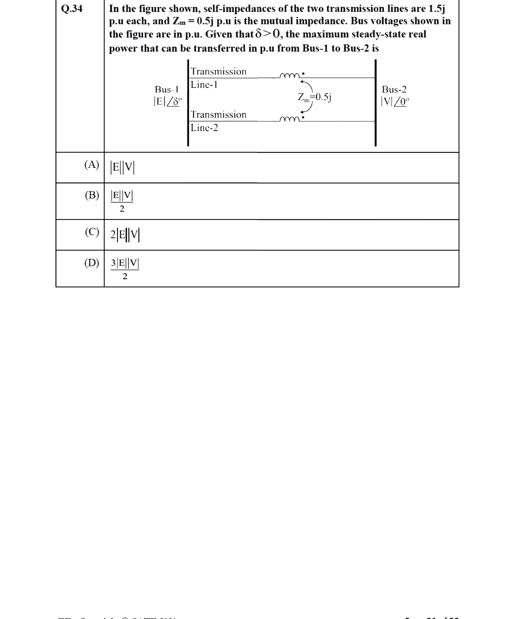
- 37EE 2021 · 2 marks · MCQ · ModerateIn the figure shown, self-impedances of the two transmission lines are each, and is the mutual impedance. Bus voltages shown in the figure are in p.u. Given that , the maximum steady-state real power that can be transferred in p.u from Bus-1 to Bus-2 is
- 38EE 2021 · 2 marks · MCQ · ModerateA 3-Bus network is shown. Consider generators as ideal voltage sources. If rows 1, 2 and 3 of the matrix correspond to Bus 1, 2 and 3, respectively, then of the network is
- 39EE 2021 · 2 marks · MCQ · ModerateSuppose , and are a set of unbalanced current phasors in a three-phase system. The phase-B zero-sequence current . If phase-A current and phase-C current , then in is
- 40EE 2020 · 1 mark · MCQ · ModerateA lossless transmission line with reactance per phase uniformly distributed along the length of the line, connecting a generator bus to a load bus, is protected up to of its length by a distance relay placed at the generator bus. The generator terminal voltage is . There is no generation at the load bus. The threshold pu current for operation of the distance relay for a solid three phase-to-ground fault on the transmission line is closest to:
- 41EE 2020 · 1 mark · MCQ · EasyOut of the following options, the most relevant information needed to specify the real power () at the PV buses in a load flow analysis is
- 42EE 2020 · 1 mark · NAT · ModerateA single synchronous generator on droop control was delivering power to a system. Due to increase in load, generator power had to be increased by , as a result of which, system frequency dropped to . Further increase in load in the system resulted in a frequency of . At this condition, the power in supplied by the generator is ____ (rounded off to 2 decimal places).
- 43EE 2020 · 2 marks · MCQ · ModerateTwo buses, and , are connected with a transmission line of admittance , at the two ends of which there are ideal transformers with turns ratios as shown. Bus admittance matrix for the system is:
- 44EE 2020 · 2 marks · NAT · ModerateBus 1 with voltage magnitude is sending reactive power towards bus 2 with voltage magnitude through a lossless transmission line of reactance . Keeping the voltage at bus 2 fixed at , magnitude of voltage at bus 1 is changed, so that the reactive power sent from bus 1 is increased by . Real power flow through the line under both the conditions is zero. The new value of the voltage magnitude, , in (rounded off to decimal places), at bus 1 is ____.
- 45EE 2020 · 2 marks · NAT · ModerateA cylindrical rotor synchronous generator has steady state synchronous reactance of and subtransient reactance of . It is operating at terminal voltage with an internal emf of . Following a three-phase solid short circuit fault at the terminal of the generator, the magnitude of the subtransient internal emf (rounded off to decimal places) is ________ .
- 46EE 2019 · 1 mark · NAT · ModerateThe matrix of a two-bus power system having two identical parallel lines connected between them in pu is given as
- 47EE 2019 · 1 mark · NAT · EasyFive alternators each rated , with of reactance on its own base are connected in parallel to a busbar. The short-circuit level in MVA at the busbar is ____.
- 48EE 2019 · 2 marks · NAT · ModerateA three-phase , transmission line is long. The line inductance is per phase, and the capacitance is per phase. The line is under open circuit condition at the receiving end and energized with at the sending end, the receiving end line voltage in (round off to two decimal places) will be ____.
- 49EE 2019 · 2 marks · NAT · ModerateA , , generator has the positive, negative, and zero sequence reactances of , , and , respectively. The neutral of the generator is grounded with a reactance so that the fault current for a bolted LG fault and that of a bolted three-phase fault at the generator terminal are equal. The value of grounding reactance in ohms (round off to one decimal place) is ____.
- 50EE 2019 · 2 marks · NAT · ModerateIn the single machine infinite bus system shown below, the generator is delivering the real power of at power factor lagging to the infinite bus. The power angle of the generator in degrees (round off to one decimal place) is ____.
- 51EE 2019 · 2 marks · NAT · ModerateIn a system, the series inductance up to the point of circuit breaker location is . The shunt capacitance at the circuit breaker terminal is . The critical value of resistance in ohms required to be connected across the circuit breaker contacts which will give no transient oscillation is _____.
- 52EE 2018 · 1 mark · MCQ · ModerateConsider a lossy transmission line with and as the sending and receiving end voltages, respectively. and are the series impedance and reactance of the line, respectively. The steady-state stability limit for the transmission line will be
- 53EE 2018 · 1 mark · NAT · EasyThe series impedance matrix of a short three-phase transmission line in phase coordinates is . If the positive sequence impedance is , and the zero sequence is , then the imaginary part of (in ) is ____ (up to 2 decimal places).
- 54EE 2018 · 1 mark · NAT · ModerateThe positive, negative and zero sequence impedances of a , three-phase, , star-grounded, generator are , and respectively on the machine rating base. The machine is unloaded and working at the rated terminal voltage. If the grounding impedance of the generator is , then the magnitude of fault current for a -phase to ground fault (in ) is ________ (up to decimal places).
- 55EE 2018 · 1 mark · NAT · EasyA bus admittance matrix for an electric power system has non-zero elements. The minimum number of branches (transmission lines and transformers) in this system are _____ (up to 2 decimal places).
- 56EE 2018 · 2 marks · MCQ · ModerateThe positive, negative and zero sequence impedances of a three phase generator are and respectively. For a line-to-line fault with fault impedance , the fault current is , where is the fault current with zero fault impedance. The relation between and is
- 57EE 2018 · 2 marks · MCQ · ModerateConsider the two bus power system network with given loads as shown in the figure. All the values shown in the figure are in per unit. The reactive power supplied by generator and are and respectively. The per unit values of , , and line reactive power loss () respectively are
- 58EE 2018 · 2 marks · MCQ · ModerateThe per-unit power output of a salient-pole generator which is connected to an infinite bus, is given by the expression, , where is the load angle. Newton-Raphson method is used to calculate the value of for . If the initial guess is , then its value (in degree) at the end of the first iteration is
- 59EE 2017 Set 2 · 1 mark · MCQ · ModerateThe figure shows the per-phase representation of a phase-shifting transformer connected between buses and . where is a complex number with non-zero real and imaginary parts.
- 60EE 2017 Set 2 · 1 mark · NAT · ModerateThe nominal- circuit of a transmission line is shown in the figure.
- 61EE 2017 Set 2 · 1 mark · NAT · ModerateIn a load flow problem solved by Newton-Raphson method with polar coordinates, the size of the Jacobian is . If there are PV buses in addition to PQ buses and a slack bus, the total number of buses in the system is ____.
- 62EE 2017 Set 2 · 2 marks · NAT · ModerateConsider an overhead transmission line with -phase, balanced system with conductors located at the vertices of an equilateral triangle of length as shown in figure below. The resistances of the conductors are neglected. The geometric mean radius (GMR) of each conductor is . Neglecting the effect of ground, the magnitude of positive sequence reactance in (rounded off to three decimal places) is ______
- 63EE 2017 Set 2 · 2 marks · NAT · ModerateA 3-phase, generator supplies power of at to a balanced 3-phase inductive load through an overhead line. The per phase line resistance and reactance are and respectively. If the voltage at the generator terminal is , the power factor of the load is ____.
- 64EE 2017 Set 2 · 2 marks · NAT · ModerateTwo generating units rated and have governor speed regulation of and respectively from no load to full load. Both the generating units are operating in parallel to share a load of . Assuming free governor action, the load shared by the larger unit is _____ .
- 65EE 2017 Set 2 · 2 marks · NAT · ModerateA 3-phase, 2-pole, , synchronous generator has a rating of , lagging. The kinetic energy of the machine at synchronous speed is . The machine is running steadily at synchronous speed and delivering power at a power angle of electrical degrees. If the load is suddenly removed, assuming the acceleration is constant for cycles, the value of the power angle after cycles is ________ electrical degrees.
- 66EE 2016 Set 2 · 1 mark · MCQ · ModerateA power system has buses including generator buses. For the load flow analysis using Newton-Raphson method in polar coordinates, the size of the Jacobian is
- 67EE 2016 Set 2 · 1 mark · MCQ · ModerateThe inductance and capacitance of a , three-phase, lossless transmission line are and respectively. The sending end voltage is maintained at . To maintain a voltage of at the receiving end, when the line is delivering load, the shunt compensation required is
- 68EE 2016 Set 2 · 1 mark · NAT · ModerateA , , , star-connected, unloaded three-phase alternator has a synchronous reactance of and a sub-transient reactance of If a 3-phase short circuit occurs close to the generator terminals, the ratio of initial and final values of the sinusoidal component of the short circuit current is ____.
- 69EE 2016 Set 2 · 2 marks · NAT · HardThe single line diagram of a balanced power system is shown in the figure. The voltage magnitude at the generator internal bus is constant and The reactances of different components in the system are also shown in the figure. The infinite bus voltage magnitude is A three phase fault occurs at the middle of line 2.
- 70EE 2016 Set 2 · 2 marks · NAT · ModerateAt no load condition, a 3-phase, , lossless power transmission line has sending-end and receiving-end voltages of and respectively. Assuming the velocity of traveling wave to be the velocity of light, the length of the line, in , is ____.
- 71EE 2016 Set 2 · 2 marks · NAT · ModerateThe power consumption of an industry is , at p.f. lagging. A synchronous motor is added to raise the power factor of the industry to unity. If the power intake of the motor is , the p.f. of the motor is ____
- 72EE 2016 Set 2 · 2 marks · NAT · HardTwo identical unloaded generators are connected in parallel as shown in the figure. Both the generators are having positive, negative and zero sequence impedances of , and , respectively. If the pre-fault voltage is , for a line-to-ground (L-G) fault at the terminals of the generators, the fault current, in , is _______