61 questions0 / 61 done
Questions per paper
- All
- MCQ
- MSQ
- NAT
2015 to 2026. Point at a year to read it.
Show as a table
| Year | All | MCQ | MSQ | NAT |
|---|---|---|---|---|
| 2015 | 0 | 0 | 0 | 0 |
| 2016 | 6 | 0 | 0 | 6 |
| 2017 | 3.5 | 2 | 0 | 1.5 |
| 2018 | 5 | 1 | 0 | 4 |
| 2019 | 6 | 2 | 0 | 4 |
| 2020 | 5 | 2 | 0 | 3 |
| 2021 | 3 | 0 | 0 | 3 |
| 2022 | 7 | 1 | 0 | 6 |
| 2023 | 4 | 1 | 1 | 2 |
| 2024 | 7 | 2 | 0 | 5 |
| 2025 | 5 | 3 | 0 | 2 |
| 2026 | 6 | 4 | 0 | 2 |
- 1EE 2026 · 1 mark · MCQ · EasyThe figure shows a straight-line approximation for the forward characteristics of a power diode. A continuous on-state current of is flowing through the diode.
- 2EE 2026 · 1 mark · MCQ · ModerateConsider the circuit shown in Figure (a). A gate pulse is applied between time instants and . After , during the MOSFET turn OFF process, it experiences a voltage overshoot.
- 3EE 2026 · 1 mark · NAT · ModerateConsider the circuit shown. Assume that the diode is ideal. The supply voltage , , and . The peak diode current (in amperes) is __________
- 4EE 2026 · 2 marks · MCQ · ModerateConsider the single-phase voltage source inverter circuit feeding an inductive load (). Assume that the power MOSFET switches are ideal. and are switched on during the first , and and are switched on during the next in a switching cycle. The switches in the same leg are thus switched in a complementary fashion. Neglect the dead time. The waveform of the inductor current () in the steady state is triangular with a peak value of as shown.
- 5EE 2026 · 2 marks · MCQ · ModerateConsider the boost converter circuit shown. Assume that the semiconductor devices are ideal. In steady state, the inductor current rises linearly from to in the first and then falls linearly from to in the next of every switching cycle as shown. The load resistance is and the capacitance is .
- 6EE 2026 · 2 marks · NAT · ModerateConsider the circuit shown. Assume that the diode () is ideal.
- 7EE 2025 · 1 mark · NAT · ModerateIn the circuit with ideal devices, the power MOSFET is operated with a duty cycle of in a switching cycle with and . The power delivered by the current source, in , is __________ (round off to the nearest integer).
- 8EE 2025 · 2 marks · MCQ · ModerateThe 3-phase modulating waveforms ( and ), used in sinusoidal PWM in a Voltage Source Inverter (VSI) are
- 9EE 2025 · 2 marks · MCQ · ModerateAn ideal sinusoidal voltage source feeds an ideal inductor through an ideal SCR with firing angle . If , then the peak of the inductor current, in ampere, is closest to
- 10EE 2025 · 2 marks · MCQ · ModerateIn the following circuit, the average voltage
- 11EE 2025 · 2 marks · NAT · ModerateThe steady state capacitor current of a conventional DC-DC buck converter, working in CCM, is shown in one switching cycle. If the input voltage is , the value of the inductor used, in , is __________ (round off to one decimal place).
- 12EE 2024 · 1 mark · MCQ · EasyIf the following switching devices have similar power ratings, which one of them is the fastest?
- 13EE 2024 · 1 mark · MCQ · ModerateA single-phase triac based AC voltage controller feeds a series RL load. The input AC supply is , . The values of and are and , respectively. The minimum triggering angle of the triac to obtain controllable output voltage is
- 14EE 2024 · 1 mark · NAT · ModerateA forced commutated thyristorized step-down chopper is shown in the figure. Neglect the ON-state drop across the power devices. Assume that the capacitor is initially charged to with the polarity shown in the figure. The load current () can be assumed to be constant at . Initially, is ON and is OFF. The turn-off time available to in microseconds, when is triggered, is ____ (rounded off to the nearest integer).
- 15EE 2024 · 2 marks · NAT · HardA single-phase half-controlled bridge converter supplies an inductive load with ripple free load current. The triggering angle of the converter is . The ratio of the rms value of the fundamental component of the input current to the rms value of the total input current of the bridge is ____ (rounded off to 3 decimal places).
- 16EE 2024 · 2 marks · NAT · EasyA single-phase full bridge voltage source inverter (VSI) feeds a purely inductive load. The inverter output voltage is a square wave in conduction mode. The fundamental frequency of the output voltage is . If the DC input voltage of the inverter is and the value of the load inductance is , the peak-to-peak load current in amperes is ____ (rounded off to the nearest integer).
- 17EE 2024 · 2 marks · NAT · ModerateIn the DC-DC converter shown in the figure, the current through the inductor is continuous. The switching frequency is . The voltage () across the load is assumed to be constant and ripple free. The peak inductor current in amperes is ____ (rounded off to the nearest integer).
- 18EE 2024 · 2 marks · NAT · ModerateA single-phase full-controlled thyristor converter bridge is used for regenerative braking of a separately excited DC motor with the following specifications:
- 19EE 2023 · 1 mark · MCQ · ModerateThe chopper circuit shown in figure (i) feeds power to a DC constant current source. The switching frequency of the chopper is . All the components can be assumed to be ideal. The gate signals of switches and are shown in figure (ii). Average voltage across the current source is
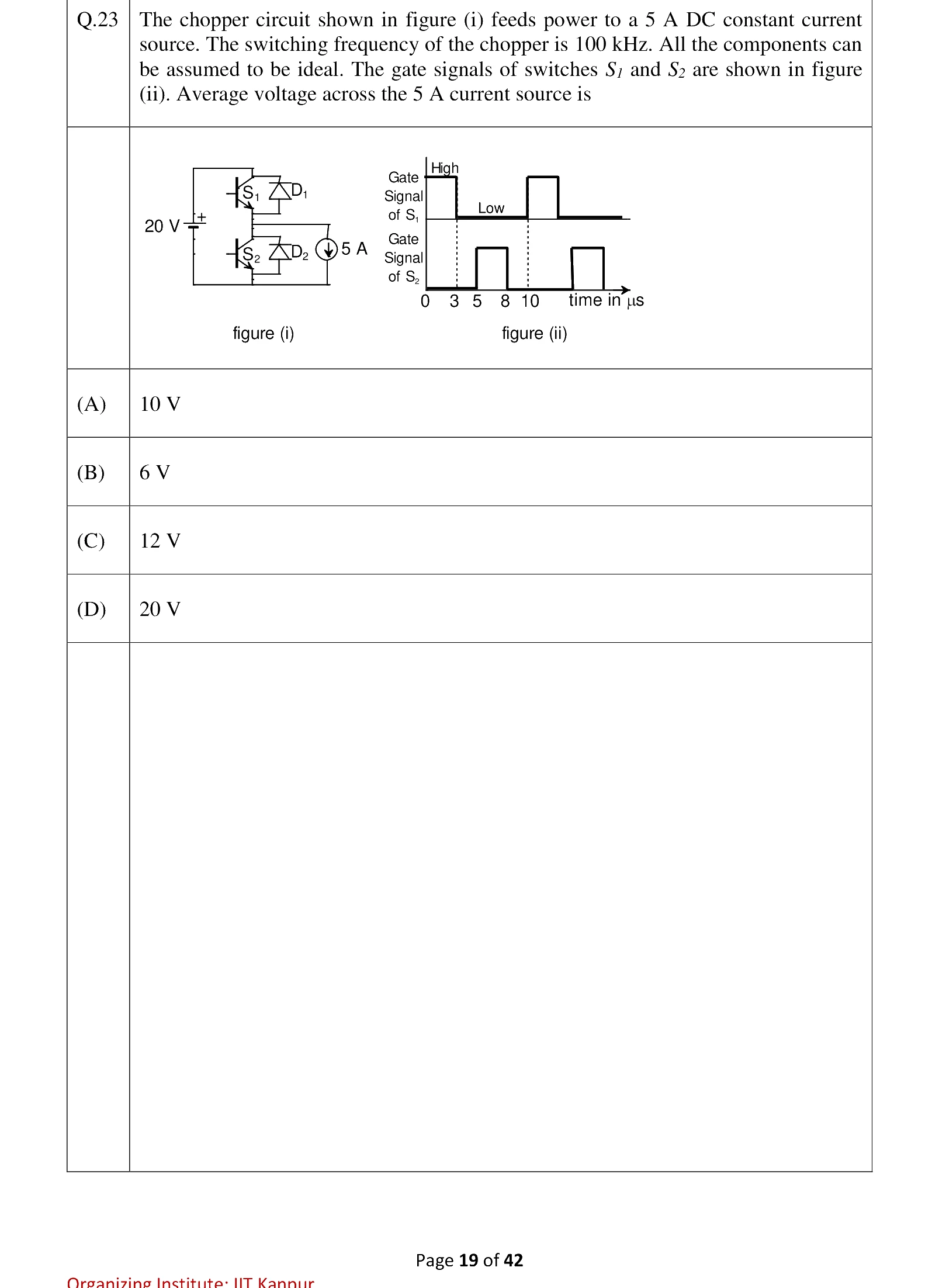
- 20EE 2023 · 1 mark · MSQ · ModerateA semiconductor switch needs to block voltage of only one polarity () during OFF state as shown in figure (i) and carry current in both directions during ON state as shown in figure (ii). Which of the following switch combination(s) will realize the same?
- 21EE 2023 · 2 marks · NAT · HardThe circuit shown in the figure has reached steady state with thyristor '' in OFF condition. Assume that the latching and holding currents of the thyristor are zero. The thyristor is turned ON at . The duration in microseconds for which the thyristor would conduct, before it turns off, is ____ (Round off to 2 decimal places).
- 22EE 2023 · 2 marks · NAT · HardThe single phase rectifier consisting of three thyristors , , and a diode feed power to a constant current load. and are fired at and is fired at . The reference for is the positive zero crossing of . The average voltage across the load in volts is ____ (Round off to 2 decimal places).
- 23EE 2022 · 1 mark · MCQ · EasyA charger supplies at for charging the battery of a laptop. The power devices, used in the converter inside the charger, operate at a switching frequency of . Which power device is best suited for this purpose?
- 24EE 2022 · 1 mark · NAT · EasyA single-phase full-bridge diode rectifier feeds a resistive load of from a , single phase AC supply. If the diodes are ideal, then the active power, in watts, drawn by the load is _____. extit{(round off to nearest integer)}
- 25EE 2022 · 1 mark · NAT · ModerateThe voltage at the input of an AC-DC rectifier is given by where . The input current drawn by the rectifier is given by
- 26EE 2022 · 2 marks · NAT · ModerateConsider an ideal full-bridge single-phase DC-AC inverter with a DC bus voltage magnitude of . The inverter output voltage shown below, is obtained when diagonal switches of the inverter are switched with duty cycle. The inverter feeds a load with a sinusoidal current given by, , where . The active power, in watts, delivered to the load is ____.
- 27EE 2022 · 2 marks · NAT · EasyFor the ideal AC-DC rectifier circuit shown in the figure below, the load current magnitude is and is ripple free. The thyristors are fired with a delay angle of . The amplitude of the fundamental component of the source current, in amperes, is ______. (round off to two decimal places)
- 28EE 2022 · 2 marks · NAT · ModerateA 3-phase grid-connected voltage source converter with DC link voltage of is switched using sinusoidal Pulse Width Modulation (PWM) technique. If the grid phase current is and the 3-phase complex power supplied by the converter is given by , then the modulation index used in sinusoidal PWM is _____. (round off to two decimal places)
- 29EE 2022 · 2 marks · NAT · HardThe steady state current flowing through the inductor of a DC-DC buck boost converter is given in the figure below. If the peak-to-peak ripple in the output voltage of the converter is , then the value of the output capacitor, in , is __________. (round off to nearest integer)
- 30EE 2021 · 2 marks · NAT · ModerateConsider the boost converter shown. Switch is operating at with a duty cycle of . Assume the diode and switch to be ideal. Under steady-state condition, the average resistance as seen by the source is
____ .
(Round off to 2 decimal places.)
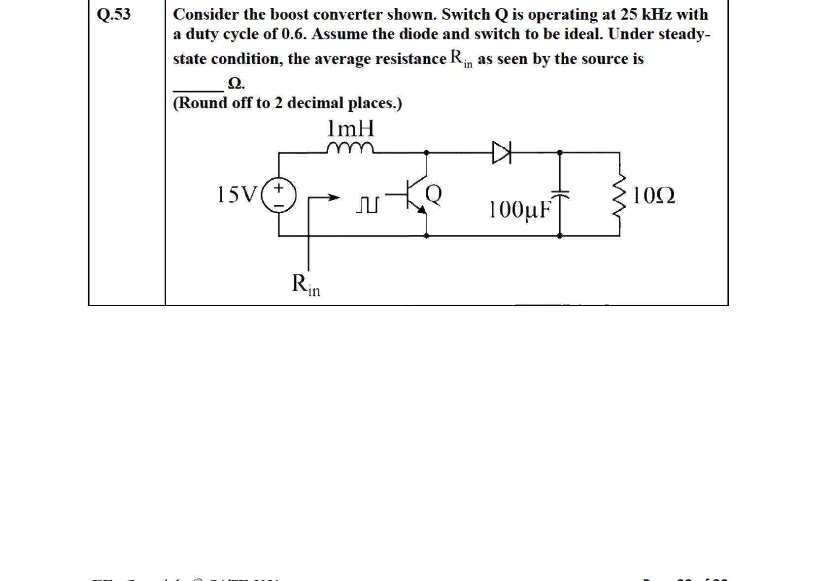
- 31EE 2021 · 2 marks · NAT · ModerateConsider the buck-boost converter shown. Switch Q is operating at and duty-cycle. Assume diode and switch to be ideal. Under steady-state condition, the average current flowing through the inductor is ____ .
- 32EE 2021 · 2 marks · NAT · ModerateA single-phase full-bridge inverter fed by a DC produces a symmetric quasi-square waveform across 'ab' as shown. To achieve a modulation index of , the angle expressed in degrees should be
____.
(Round off to decimal places.)
(Modulation index is defined as the ratio of the peak of the fundamental component of to the applied DC value.)
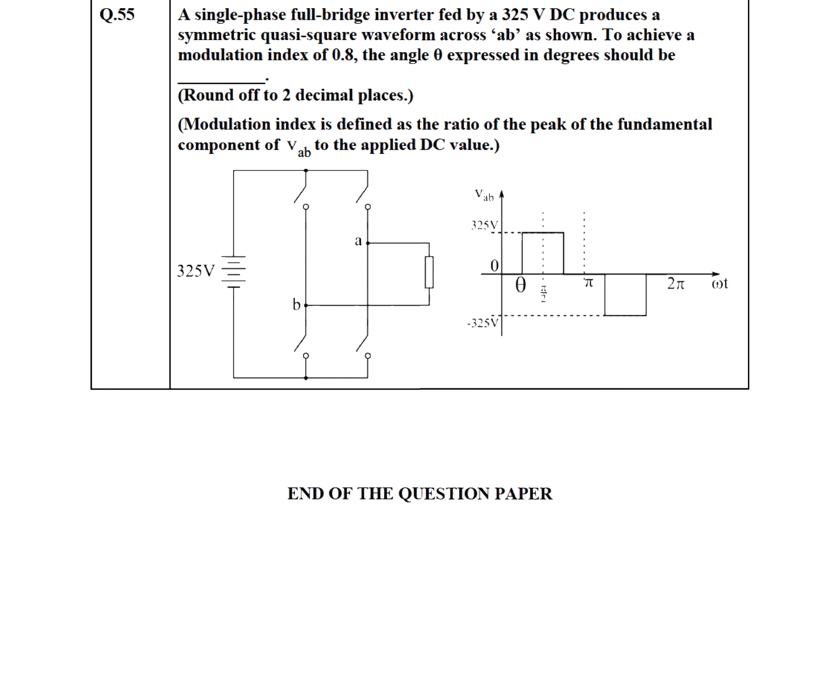
- 33EE 2020 · 1 mark · MCQ · ModerateA single-phase, full-bridge diode rectifier fed from a , sinusoidal source supplies a series combination of finite resistance, , and a very large inductance, . The two most dominant frequency components in the source current are:
- 34EE 2020 · 1 mark · MCQ · ModerateThyristor is triggered at an angle (in degree), and at angle , in each cycle of the sinusoidal input voltage. Assume both thyristors to be ideal. To control the load power over the range to , the minimum range of variation in is:
- 35EE 2020 · 1 mark · NAT · ModerateA single-phase inverter is fed from a dc source and is controlled using a quasi-square wave modulation scheme to produce an output waveform, , as shown. The angle is adjusted to entirely eliminate the harmonic component from the output voltage. Under this condition, for , the magnitude of the harmonic component as a percentage of the magnitude of the fundamental component is ____ (rounded off to decimal places).
- 36EE 2020 · 2 marks · NAT · ModerateIn the dc-dc converter circuit shown, switch is switched at a frequency of with a duty ratio of . All components of the circuit are ideal, and the initial current in the inductor is zero. Energy stored in the inductor in (rounded off to decimal places) at the end of complete switching cycles is ________.
- 37EE 2020 · 2 marks · NAT · ModerateA single-phase, full-bridge, fully controlled thyristor rectifier feeds a load comprising a resistance in series with a very large inductance. The rectifier is fed from an ideal , sinusoidal source through cables which have negligible internal resistance and a total inductance of . If the thyristors are triggered at an angle , the commutation overlap angle in degree (rounded off to 2 decimal places) is ____.
- 38EE 2019 · 1 mark · MCQ · EasyA six-pulse thyristor bridge rectifier is connected to a balanced three-phase, AC source. Assuming that the DC output current of the rectifier is constant, the lowest harmonic component in the AC input current is
- 39EE 2019 · 1 mark · NAT · ModerateThe output voltage of a single-phase full bridge voltage source inverter is controlled by unipolar PWM with one pulse per half cycle. For the fundamental rms component of output voltage to be of DC voltage, the required pulse width in degrees (round off up to one decimal place) is ____.
- 40EE 2019 · 2 marks · MCQ · ModerateA DC-DC buck converter operates in continuous conduction mode. It has input voltage, and it feeds a resistive load of . The switching frequency of the converter is . If switch-on duration is , the load power is
- 41EE 2019 · 2 marks · NAT · ModerateIn a DC-DC boost converter, the duty ratio is controlled to regulate the output voltage at . The input DC voltage is . The output power is . The switching frequency is . Assume ideal components and a very large output filter capacitor. The converter operates at the boundary between continuous and discontinuous conduction modes. The value of the boost inductor (in ) is _____.
- 42EE 2019 · 2 marks · NAT · EasyA fully-controlled three-phase bridge converter is working from a , AC supply. It is supplying constant current of at to a DC load. Assume large inductive smoothing and neglect overlap. The rms value of the AC line current in amperes (round off to two decimal places) is ____.
- 43EE 2019 · 2 marks · NAT · ModerateA single-phase fully-controlled thyristor converter is used to obtain an average voltage of with constant current to feed a DC load. It is fed from single-phase AC supply of , . Neglect the source impedance. The power factor (round off to two decimal places) of AC mains is ______.
- 44EE 2018 · 1 mark · MCQ · ModerateFour power semiconductor devices are shown in the figure along with their relevant terminals. The device(s) that can carry dc current continuously in the direction shown when gated appropriately is (are)
- 45EE 2018 · 1 mark · NAT · ModerateThe waveform of the current drawn by a semi-converter from a sinusoidal AC voltage source is shown in the figure. If , the rms value of fundamental component of the current is ________ (up to 2 decimal places).
- 46EE 2018 · 2 marks · NAT · ModerateA phase controlled single phase rectifier, supplied by an AC source, feeds power to an R-L-E load as shown in the figure. The rectifier output voltage has an average value given by , where and is the firing angle. If the power delivered to the lossless battery is , in degree is_____ (up to 2 decimal places).
- 47EE 2018 · 2 marks · NAT · ModerateThe figure shows two buck converters connected in parallel. The common input dc voltage for the converters has a value of . The converters have inductors of identical value. The load resistance is . The capacitor voltage has negligible ripple. Both converters operate in the continuous conduction mode. The switching frequency is , and the switch control signals are as shown. The circuit operates in the steady state. Assuming that the converters share the load equally, the average value of , the current of switch S1 (in Ampere), is ____ (up to 2 decimal places).
- 48EE 2018 · 2 marks · NAT · ModerateA dc to dc converter shown in the figure is charging a battery bank, whose voltage is constant at . is another battery bank whose voltage is constant at . The value of the inductor, is and the ideal switch, is operated with a switching frequency of with a duty ratio of . Once the circuit has attained steady state and assuming the diode to be ideal, the power transferred from to (in ) is ____ (up to 2 decimal places).
- 49EE 2017 Set 2 · 1 mark · MCQ · EasyA phase-controlled, single-phase, full-bridge converter is supplying a highly inductive DC load. The converter is fed from a , AC source. The fundamental frequency in of the voltage ripple on the DC side is
- 50EE 2017 Set 2 · 1 mark · MCQ · ModerateIn the circuit shown, the diodes are ideal, the inductance is small, and . Which one of the following statements is true?
- 51EE 2017 Set 2 · 1 mark · MCQ · ModerateA three-phase voltage source inverter with ideal devices operating in conduction mode is feeding a balanced star-connected resistive load. The DC voltage input is . The peak of the fundamental component of the phase voltage is
- 52EE 2017 Set 2 · 1 mark · NAT · HardThe figure below shows the circuit diagram of a controlled rectifier supplied from a , , -phase voltage source and a ideal transformer. Assume that all devices are ideal. The firing angles of the thyristors and are and , respectively.
- 53EE 2017 Set 2 · 2 marks · MCQ · ModerateThe figure below shows a half-bridge voltage source inverter supplying an RL-load with and . The desired fundamental frequency of the load voltage is . The switch control signals of the converter are generated using sinusoidal pulse width modulation with modulation index . At , the RL-load draws an active power of . The value of DC source voltage in volts is
- 54EE 2017 Set 2 · 2 marks · NAT · ModerateIn the circuit shown in the figure, the diode used is ideal. The input power factor is ________. (Give the answer up to two decimal places.)
- 55EE 2017 Set 2 · 2 marks · NAT · ModerateIn the circuit shown all elements are ideal and the switch is operated at and duty ratio. The capacitor is large enough so that the ripple across it is negligible and at steady state acquires a voltage as shown. The peak current in amperes drawn from the DC source is ____ . (Give the answer up to one decimal place.)
- 56EE 2016 Set 2 · 1 mark · NAT · ModerateA three-phase diode bridge rectifier is feeding a constant DC current of to a highly inductive load. If three-phase, , AC source is supplying to this bridge rectifier then the rms value of the current in each diode, in ampere, is ____.
- 57EE 2016 Set 2 · 1 mark · NAT · EasyA buck-boost DC-DC converter, shown in the figure below, is used to convert battery voltage to DC voltage to feed a load of . It is operated at with an inductor of and output capacitor of . All devices are considered to be ideal. The peak voltage across the solid-state switch (S), in volt, is _____.
- 58EE 2016 Set 2 · 2 marks · NAT · ModerateA full-bridge converter supplying an RLE load is shown in figure. The firing angle of the bridge converter is . The supply voltage , , . The inductor L is large enough to make the output current a smooth dc current. Switches are lossless. The real power fed back to the source, in kW, is ________.
- 59EE 2016 Set 2 · 2 marks · NAT · ModerateA three-phase Voltage Source Inverter (VSI) as shown in the figure is feeding a delta connected resistive load of . If it is fed from a battery, with conduction of solid-state devices, the power consumed by the load, in , is ____.
- 60EE 2016 Set 2 · 2 marks · NAT · ModerateA DC-DC boost converter, as shown in the figure below, is used to boost to , at a power of . All devices are ideal. Considering continuous inductor current, the rms current in the solid state switch (), in ampere, is ____.
- 61EE 2016 Set 2 · 2 marks · NAT · HardA single-phase bi-directional voltage source converter (VSC) is shown in the figure below. All devices are ideal. It is used to charge a battery at with power of from a source (rms), sinusoidal AC mains at unity p.f. If its AC side interfacing inductor is and the switches are operated at , then the phase shift () between AC mains voltage () and fundamental AC rms VSC voltage (), in degree, is _______