55 questions0 / 55 done
Questions per paper
- All
- MCQ
- MSQ
- NAT
2021 to 2026. Point at a year to read it.
Show as a table
| Year | All | MCQ | MSQ | NAT |
|---|---|---|---|---|
| 2021 | 0 | 0 | 0 | 0 |
| 2022 | 6 | 5 | 0 | 1 |
| 2023 | 15 | 11 | 0 | 4 |
| 2024 | 11 | 4 | 2 | 5 |
| 2025 | 9 | 7 | 2 | 0 |
| 2026 | 14 | 10 | 1 | 3 |
- 1EC 2026 · 1 mark · MCQ · ModerateThe Laplace Transform of the signal is given by which of the following expressions?\n\n[“” represents convolution operator]
- 2EC 2026 · 1 mark · MCQ · ModerateTwo analog signals and ( in second), are sampled at a rate , where
- 3EC 2026 · 1 mark · MCQ · ModerateThe response of a discrete time system obeys the following relation:
- 4EC 2026 · 1 mark · MCQ · ModerateThe relation between the input current () and the output voltage () of a circuit is governed by the equation: . The circuit is excited by , where is a real valued constant. at is .
- 5EC 2026 · 1 mark · NAT · ModerateThe output voltage (in Volt) for the network given in the Figure is ___.
- 6EC 2026 · 1 mark · NAT · ModerateConsider the circuit shown in the Figure, where the input is in Volt.
- 7EC 2026 · 1 mark · NAT · ModerateFor a lossless passive two-port network, and intersect at .
- 8EC 2026 · 2 marks · MCQ · ModerateThe continuous time signal is real, periodic with period and satisfies the Dirichlet conditions.
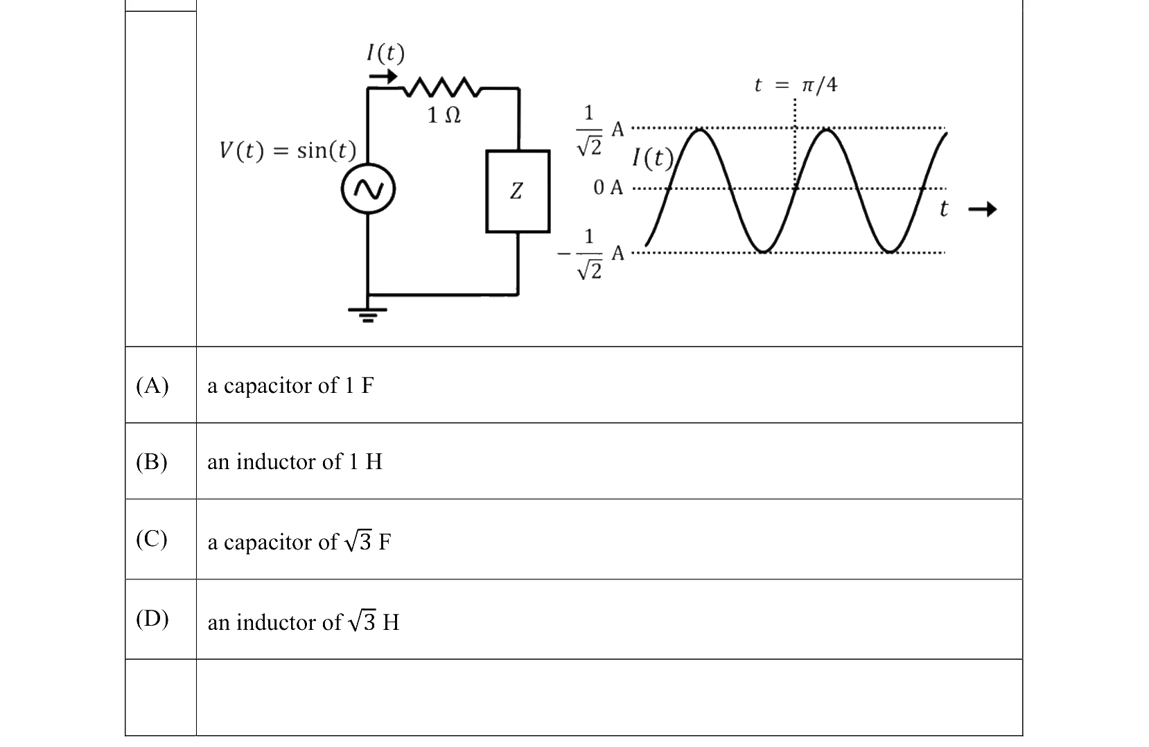
- 9EC 2026 · 2 marks · MCQ · ModerateIn the given circuit, and . The phasor diagram for and is also shown. Assume that the phase is at a frequency of .
- 10EC 2026 · 2 marks · MCQ · ModerateConsider a real signal , such that
- 11EC 2026 · 2 marks · MCQ · HardConsider a real baseband signal , for (in seconds) .
- 12EC 2026 · 2 marks · MCQ · EasyConsider the discrete time system () with input and output as shown in the Figure. The two sub-systems represented by their impulse responses and are linear and time invariant.
- 13EC 2026 · 2 marks · MCQ · ModerateConsider the two-port network as shown in the Figure.
- 14EC 2026 · 2 marks · MSQ · ModerateLet and represent two sinusoids for a positive integer and .
- 15EC 2025 · 1 mark · MCQ · ModerateConsider the discrete-time system below with input and output . In the figure, and denote the impulse responses of LTI Subsystems 1 and 2, respectively. Also, is the unit impulse, and .
- 16EC 2025 · 1 mark · MCQ · EasyConsider a continuous-time, real-valued signal whose Fourier transform exists.
- 17EC 2025 · 1 mark · MCQ · EasyConsider a part of an electrical network as shown below. Some node voltages, and the current flowing through the resistor are as indicated.
- 18EC 2025 · 1 mark · MCQ · EasyLet , , and be the currents flowing through the capacitor, inductor, and resistor, respectively, in the circuit given below. The AC admittances are given in Siemens (S).
- 19EC 2025 · 1 mark · MSQ · ModerateLet be a discrete-time signal whose -transform is .
- 20EC 2025 · 2 marks · MCQ · ModerateConsider a continuous-time finite-energy signal whose Fourier transform vanishes outside the frequency interval , where is in rad/sec.
- 21EC 2025 · 2 marks · MCQ · ModerateIn the circuit below, is an ideal AC voltmeter and is an ideal AC ammeter. The source voltage (in Volts) is .
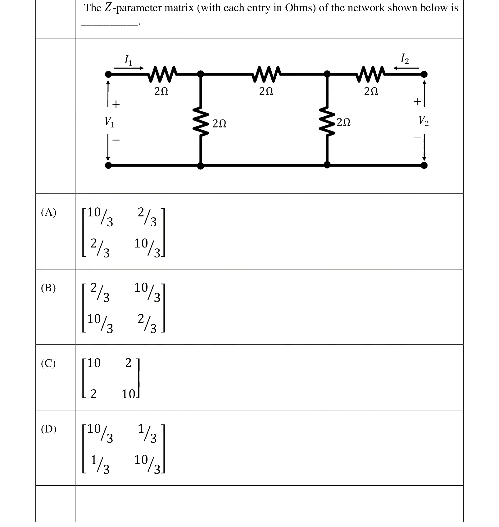
- 22EC 2025 · 2 marks · MCQ · ModerateThe -parameter matrix of a two port network relates the port voltages and port currents as follows:
The -parameter matrix (with each entry in Ohms) of the network shown below is _______.
- 23EC 2025 · 2 marks · MSQ · ModerateLet be a periodic signal with fundamental period . Consider the signal , where .
- 24EC 2024 · 1 mark · MCQ · EasyA causal and stable LTI system with impulse response produces an output for an input signal . A signal is applied to another causal and stable LTI system with impulse response . The resulting output is ____.
- 25EC 2024 · 1 mark · MCQ · ModerateIn the circuit shown, the step-down transformer and the diodes are ideal. The diodes have no voltage drop in forward biased condition. If the input voltage (in Volts) is and the average value of load voltage (in Volts) is , the value of is ____.
- 26EC 2024 · 1 mark · MSQ · ModerateFor a causal discrete-time LTI system with transfer function which of the following statements is/are true?
- 27EC 2024 · 1 mark · NAT · ModerateIn the given circuit, the current (in mA) is ______.
- 28EC 2024 · 1 mark · NAT · ModerateIn the circuit given below, the switch S was kept open for a sufficiently long time and is closed at time . The time constant (in seconds) of the circuit for is ________.
- 29EC 2024 · 2 marks · MCQ · ModerateConsider two continuous time signals and as shown below
- 30EC 2024 · 2 marks · MCQ · HardA continuous signal is sampled at a rate of . The sampled signal when passed through an LTI system with impulse response
- 31EC 2024 · 2 marks · MSQ · ModerateThe radian frequency value(s) for which the discrete time sinusoidal signal has a period of 40 is/are ______.
- 32EC 2024 · 2 marks · NAT · EasyThe relationship between any -length sequence and its corresponding -point discrete Fourier transform is defined as
- 33EC 2024 · 2 marks · NAT · ModerateFor the two port network shown below, the value of the parameter (in Siemens) is ______.
- 34EC 2024 · 2 marks · NAT · ModerateIn the network shown below, maximum power is to be transferred to the load .
- 35EC 2023 · 1 mark · MCQ · ModerateA series circuit has a quality factor of at a center frequency of . The possible values of , and are
- 36EC 2023 · 1 mark · MCQ · ModerateConsider a system with input and output . The system is
- 37EC 2023 · 1 mark · MCQ · ModerateLet be a strictly band-limited signal with bandwidth and energy . Assuming , the energy in the signal is
- 38EC 2023 · 1 mark · MCQ · ModerateThe Fourier transform of is
- 39EC 2023 · 1 mark · MCQ · EasyIn the table shown below, match the signal type with its spectral characteristics.
- 40EC 2023 · 1 mark · NAT · ModerateIn the circuit shown below, the current flowing through resistor is ____ (rounded off to two decimal places).
- 41EC 2023 · 1 mark · NAT · ModerateFor the two port network shown below, the -parameters is given as
- 42EC 2023 · 1 mark · NAT · ModerateIn the circuit shown below, switch was closed for a long time. If the switch is opened at , the maximum magnitude of the voltage , in volts, is _____ (\textit{rounded off to the nearest integer}).
- 43EC 2023 · 2 marks · MCQ · ModerateThe switch was closed and was open for a long time. At , switch is opened and is closed, simultaneously. The value of , in amperes, is
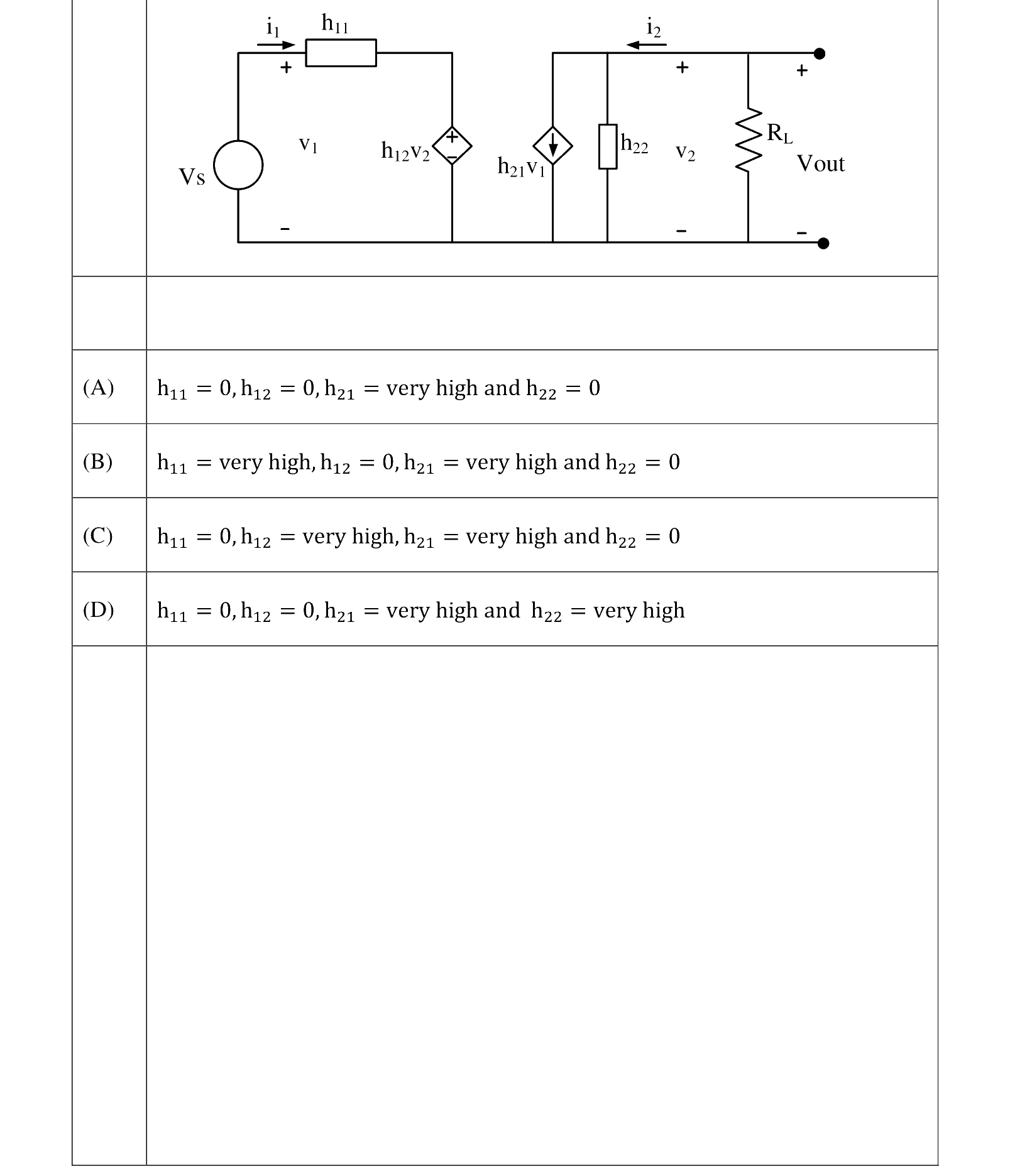
- 44EC 2023 · 2 marks · MCQ · ModerateThe h-parameters of a two port network are shown below. The condition for the maximum small signal voltage gain is
- 45EC 2023 · 2 marks · MCQ · ModerateConsider a discrete-time periodic signal with period . Let the discrete-time Fourier series (DTFS) representation be , where and . The value of the sum is
- 46EC 2023 · 2 marks · MCQ · EasyLet an input having discrete time Fourier transform be passed through an LTI system. The frequency response of the LTI system is . The output of the system is
- 47EC 2023 · 2 marks · MCQ · HardLet be passed through an LTI system having impulse response . The output of the system is
- 48EC 2023 · 2 marks · MCQ · ModerateLet and be two band-limited signals having bandwidth each. In the figure below, the Nyquist sampling frequency, in , required to sample , is
- 49EC 2023 · 2 marks · NAT · ModerateLet and is shown in the figure below. For , the is _____________________ (rounded off to the nearest integer).
- 50EC 2022 · 1 mark · MCQThe current in the circuit shown is ______.
- 51EC 2022 · 1 mark · MCQThe Fourier transform of the signal is ____.
- 52EC 2022 · 1 mark · MCQIn a circuit, there is a series connection of an ideal resistor and an ideal capacitor. The conduction current (in Amperes) through the resistor is . The displacement current (in Amperes) through the capacitor is _______.
- 53EC 2022 · 1 mark · NATLet and , where denotes the unit step function.
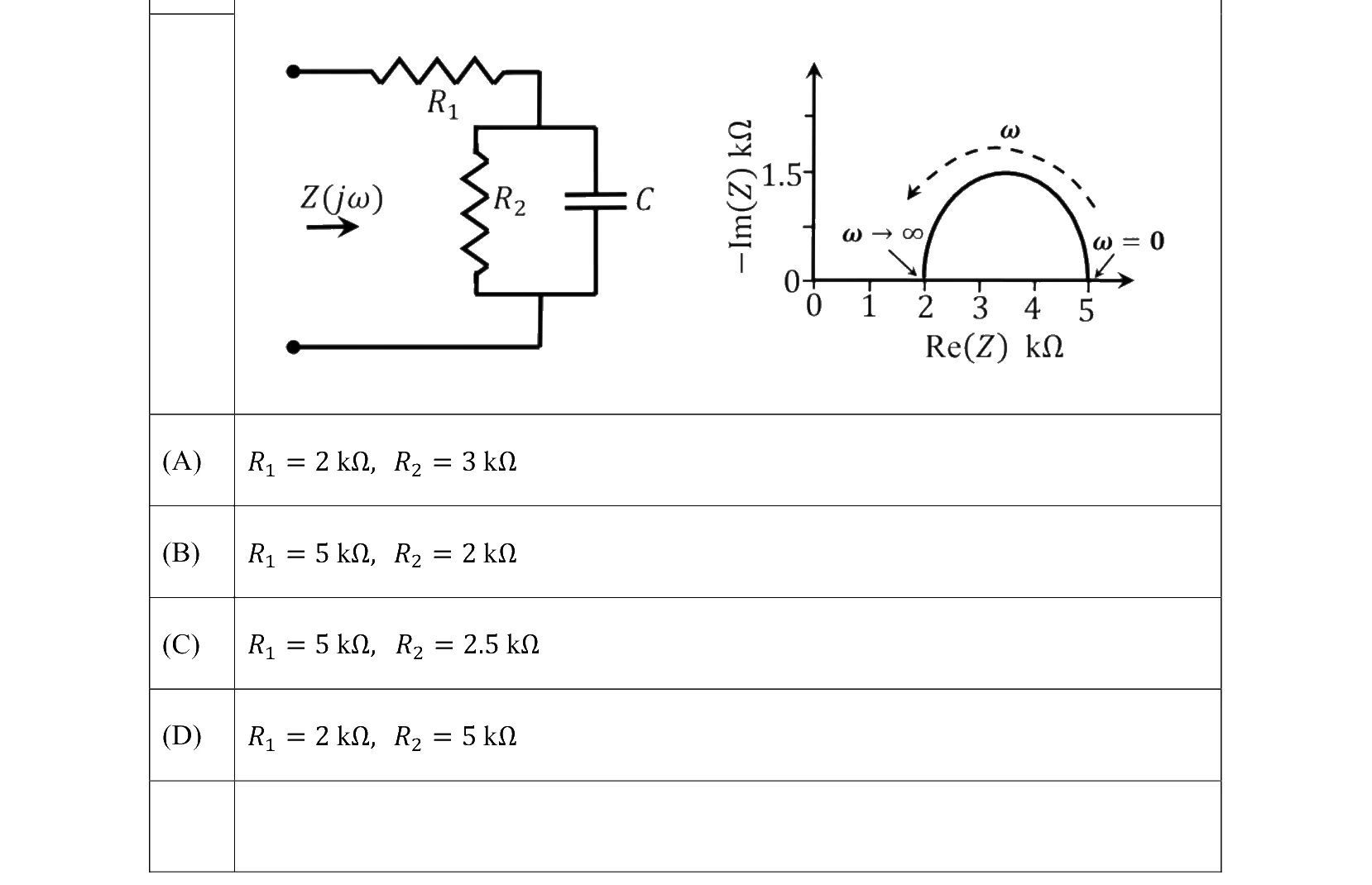
- 54EC 2022 · 2 marks · MCQFor the circuit shown, the locus of the impedance is plotted as increases from zero to infinity. The values of and are:
- 55EC 2022 · 2 marks · MCQConsider the circuit shown in the figure with input in volts. The sinusoidal steady state current flowing through the circuit is shown graphically (where is in seconds). The circuit element can be ____.\n\n