Analog Circuits0 / 9 done
Questions per paper
- All
- MCQ
- MSQ
- NAT
2021 to 2026. Point at a year to read it.
Show as a table
| Year | All | MCQ | MSQ | NAT |
|---|---|---|---|---|
| 2021 | 0 | 0 | 0 | 0 |
| 2022 | 2 | 1 | 1 | 0 |
| 2023 | 2 | 2 | 0 | 0 |
| 2024 | 0 | 0 | 0 | 0 |
| 2025 | 2 | 0 | 1 | 1 |
| 2026 | 3 | 2 | 0 | 1 |
- 1EC 2026 · 1 mark · MCQ · ModerateThe ideal OP-AMP circuit shown in the Figure produces output voltage
- 2EC 2026 · 2 marks · MCQ · ModerateA circuit using an ideal OP-AMP is shown in the Figure.
- 3EC 2026 · 2 marks · NAT · ModerateConsider an ideal OP-AMP circuit as shown in the Figure.
- 4EC 2025 · 1 mark · MSQ · EasyWhich of the following statements is/are TRUE with respect to an ideal opamp?
- 5EC 2025 · 1 mark · NAT · ModerateAll the components in the bandpass filter given below are ideal. The lower frequency of the filter is .
- 6EC 2023 · 1 mark · MCQ · EasyA cascade of common-source amplifiers in a unity gain feedback configuration oscillates when
- 7EC 2023 · 2 marks · MCQ · ModerateThe of the circuit shown below is
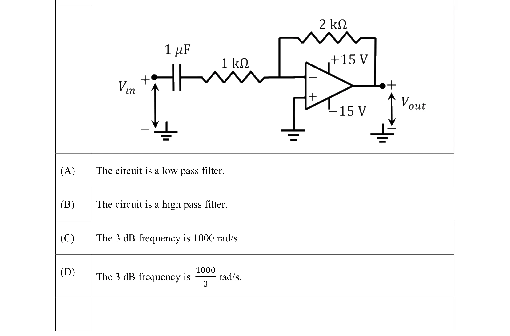
- 8EC 2022 · 1 mark · MSQAn ideal OPAMP circuit with a sinusoidal input is shown in the figure. The frequency is the frequency at which the magnitude of the voltage gain decreases by from the maximum value. Which of the options is/are correct?
- 9EC 2022 · 2 marks · MCQA circuit with an ideal OPAMP is shown. The Bode plot for the magnitude (in dB) of the gain transfer function () of the circuit is also provided (here, is the angular frequency in ). The values of and are _________.